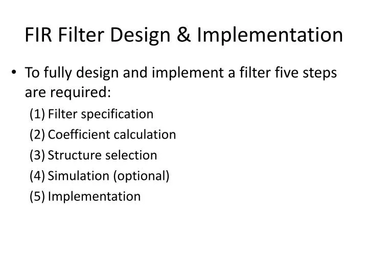
Of EECS Now for anytypeof filter we can improve roll-off ie increase stop-band attenuation by increasing the filter orderN. It makes phase responseS.

Filter Design 1 Jack Ou Es590 Outline Butterworth Lpf Design Example Lpf To Hpf Conversion Lpf To Bpf Conversi Filter Design Transfer Function Acoustic Wave
Investigate which transmission lines can be used to implement RF and Microwave filters.
. 50 Ohm Cutoff frequency Fc. Design and implement the filters using the transmission line s and connectors. 40 dB at 2Fc.
In most microwave applications filters are designed to operate between 50 Ω source and load impedances. Design a LC bandpass filter. The image parameter method of filter design was developed in the late 1930s and was useful for low-frequency filters in radio and telephony.
The image impedances are Z i1 and Z i2 Microwave Circuits Design. Low-pass High-pass BandstopBandpass 19. Design of Microwave Filters The first step in the design of microwave filters is to select a suitable approximation of the prototype model based on the specifications.
EEE 211 Microwave Engineering I. Microwaves of this range 25 GHz change the direction of electromagnetic fields 2500000000 times in 1 second Consequently the heat efficiency of a microwave oven is greatly high Applications of Microwaves Microwave Oven 245 GHz 600W the radio waves penetrate the food and excite water and fat molecules pretty much evenly throughout the food There is no. The cut-off frequency f c is defined at 3 dB attenuation Full size image.
Fundamentals of Microwave and RF Design enables mastery of the essential concepts required to cross the barriers to a successful career in microwave and RF design. Microwave Engineering 2. Band Pass Filters 1 - Anatech Electronics is an ISO 90012015 certified company offers Standard Band Pass Filters database contains previously designed band pass filters in a variety of technologies including Cavity Band Pass Filters Waveguide Band Pass Filters Ceramic Band Pass Filters and Lumped Elements Band Pass Filters SAW band pass filters Helical band.
The example mentioned here is for micro-strip based LP filter. Ppt Microwave Filter Design Powerpoint Presentation Free Download Id 332301 MICROWAVE AND RADAR ENGINEERING By M. RF Filter design example.
We will take up all kinds of repairs and services of your microwave oven. Filter Design By the Image Parameter Method Z i1 input impedance at port 1 when port 2 is terminated with Z i2 Z i2 input impedance at port 2 when port 1 is terminated with Z i1 For a reciprocal two- port network on the right it can be specified by its ABCDparameters. Filter design Example Design 5-poles low pass filter with a cutoff frequency of 2 GHz impedance 50 Ohms insertion loss 15 dB at 3 GHz g1 0618 g 2 1618 g3 2 g 4 1618 g 5 0618 Maximally flat response 37 EM Wave Lab.
Extensive treatment of scattering parameters that naturally describe power flow and of Smith-chart-based design procedures prepare the student for success. EE433-08 Planer Microwave Circuit Design Notes i A Brief Introduction To Microwave Engineering and To EE 433 The microwave region is typically defined as those frequencies between 300 MHz and 300 GHz. Our technicians are experts in identifying the any kind of faults in any type of microwave oven.
Components shaded in red are the source and load impedances of the system. Introduction to SAW Filter Theory Design Techniques Figure 6. 6 1-13-2003 p 3 3.
Filters Filters are two-port networks used to attenuate undesirable frequencies. 14 Scope of Study In this project knowledge on microwave filter designing would be required. Designing a high -power microwave amplifier that is illustrated in the book Microwave Circuit Design Using Linear and Nonlinear Techniques by Vendelin Pavio and Rohde.
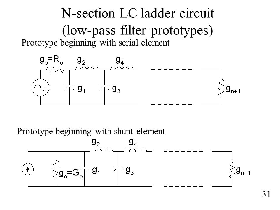
Model of Periodic Structure. From the element values of lowpass prototype step 2. A filter is a reactive network that passes a desired band of frequencies while almost stopping all other bands of frequencies.
To come out with a simple and straight-forward mathematical model that could enable the different kinds of responses for the synthesis of the ladder network. Microwave filters are commonly used in transceiver circuits. The design can be with the aid of the Smith Chart.
Diagram for a simple filter or delay line. To illustrate RF filter design we will take RF Low Pass Filter with the following specifications. Filter Design by Insertion Loss Method.
However be aware that increasing the filter order likewise has these deleteriouseffects. The filter specifications are illustrated in Fig. The UWB bandpass filter operating in the 36 GHz to 106 GHz frequency band is targeted to comply with the FCC spectral mask for UWB systems.
Specially made for such appliances that it helps to automatically cut the grid supply during power surges and fluctuations. In the lumped and distributed form they are extensively used for both commercial and military applications. The four basic filter types are low-pass high-pass bandpass and bandstop.
Microwave filters play an important role in any RF front end for the suppression of out of band signals. Morgan Wiley Handbook of RFMicrowave Components and Engineering Ch. An automatic stabilizer that stabilizes the power supply to your appliances such as washing machine microwave oven treadmill small home appliances and kitchen appliances.
Utilized in various filter models of different orders. The example mentioned here is for micro-strip based LP filter. Determine which filter types can be built using the transmiss ion lines.
Apply bandpass transformation using J-inverters Step 4. This design method is based stric tly on using small -signal S -parameters for the design of M1 the input matching circuit and M2 the output matching circuit. Microwave communication radar or test and measurement system.
IFB Microwave Oven Repair Service Center in Hyderabad And we are giving our best and quality services and repairs in Hyderabad from many years. A low-pass filter is characterized by the insertion loss versus frequency plot in Figure. Today most microwave filter design is done with sophisticated computer-aided design CAD packages based on the insertion loss method.
52 A high pass filter response showing definitions of the figure of merit. Apply impedance scaling step 3. 312005 Microwave Filter Designdoc 67 Jim Stiles The Univ.
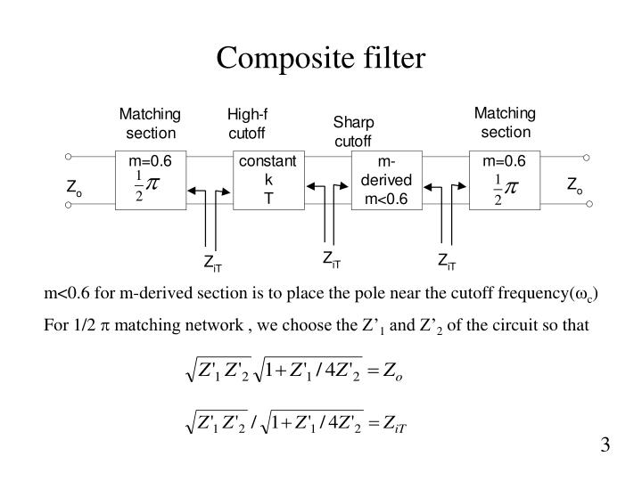
The prototype filter is composed of quarter-. This article describes basic steps in microwave and RF filter design. 50Ω system impedance is typical for most SAW applications.
In this thesis ultra-wideband UWB microwave filters and design challenges are studied anda microstrip UWB filter prototype design is presented. Recall 1 MHz 1x10⁶ Hz and 1 GHz 1x10⁹ Hz These frequencies include free-space wavelengths between 1 m and 1 mm. Filter Techniques Applied to Antenna Design Theory The return loss expression of the equivalent circuit of dual mode patch antenna is For 6dB bandwidth it can be shown using dual mode filter theory that the bandwidth can be optimum if J01 2 J12 5296 J23 3898 and J34 2976.
The terms of reference of this thesis are as follows. The f0 is 28 GHz bandwidth is 500 MHz and the input and output impedance 50.

Lecture Rf Microwave Filters Ppt Download
Microwave Filter Design Ppt Download

Microwave Filter Design Ppt Download

Chapter 8 Microwave Filters Ppt Download
Ppt Microwave Filter Design Powerpoint Presentation Free Download Id 332301
Ppt Microwave Filter Design Powerpoint Presentation Free Download Id 332301
Ppt Fir Filter Design Implementation Powerpoint Presentation Free Download Id 3658573

Design Of Rf And Microwave Filters Ppt Video Online Download
0 comments
Post a Comment